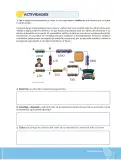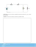

















Diseña un circuito con al menos seis resistencias, en configuración serie-paralelo, con valores comerciales; dibuja el circuito y resuélvelo manualmente (luego verifica con un simulador).
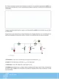
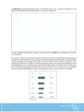
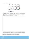
Solución orientativa (ejemplo de circuito válido): se propone una fuente de V = 12 \, \text{V}, R_1 = 100 \, \Omega en serie con el resto del circuito, y dos bloques en paralelo (R_2 = 220 \, \Omega con R_3 = 100 \, \Omega; y R_4 = 47 \, \Omega con R_5 = 22 \, \Omega), seguidos de R_6 = 330 \, \Omega en serie. Total: 6 resistencias, todos los valores comerciales de la serie E24.
Equivalente del bloque 1 (R_2 \parallel R_3): R_{23} = \frac{R_2 \cdot R_3}{R_2 + R_3} = \frac{220 \cdot 100}{220 + 100} = \frac{22\,000}{320} = 68{,}75 \, \Omega
Equivalente del bloque 2 (R_4 \parallel R_5): R_{45} = \frac{R_4 \cdot R_5}{R_4 + R_5} = \frac{47 \cdot 22}{47 + 22} = \frac{1\,034}{69} \approx 15{,}0 \, \Omega
Resistencia total (todo está en serie): R_T = R_1 + R_{23} + R_{45} + R_6 = 100 + 68{,}75 + 15{,}0 + 330 = 513{,}75 \, \Omega \approx 514 \, \Omega
Corriente total (Ley de Ohm): I_T = \frac{V}{R_T} = \frac{12 \, \text{V}}{513{,}75 \, \Omega} \approx 0{,}0234 \, \text{A} = 23{,}4 \, \text{mA}
Caídas de tensión en serie (son las mismas corrientes): V_1 = I_T \cdot R_1 = 23{,}4 \, \text{mA} \cdot 100 \, \Omega = 2{,}34 \, \text{V} V_{23} = I_T \cdot R_{23} = 23{,}4 \, \text{mA} \cdot 68{,}75 \, \Omega \approx 1{,}61 \, \text{V} V_{45} = I_T \cdot R_{45} = 23{,}4 \, \text{mA} \cdot 15{,}0 \, \Omega \approx 0{,}35 \, \text{V} V_6 = I_T \cdot R_6 = 23{,}4 \, \text{mA} \cdot 330 \, \Omega \approx 7{,}71 \, \text{V} Comprobación (Ley de Kirchhoff de voltajes): 2{,}34 + 1{,}61 + 0{,}35 + 7{,}71 = 12{,}01 \, \text{V} \approx 12 \, \text{V} \quad \checkmark
Corrientes parciales dentro de cada bloque en paralelo: I_2 = \frac{V_{23}}{R_2} = \frac{1{,}61 \, \text{V}}{220 \, \Omega} \approx 7{,}32 \, \text{mA}, \qquad I_3 = \frac{V_{23}}{R_3} = \frac{1{,}61 \, \text{V}}{100 \, \Omega} = 16{,}1 \, \text{mA} I_2 + I_3 = 7{,}32 + 16{,}1 = 23{,}4 \, \text{mA} = I_T \quad \checkmark \ \text{(Ley de Kirchhoff de corrientes)} I_4 = \frac{V_{45}}{R_4} = \frac{0{,}35 \, \text{V}}{47 \, \Omega} \approx 7{,}45 \, \text{mA}, \qquad I_5 = \frac{V_{45}}{R_5} = \frac{0{,}35 \, \text{V}}{22 \, \Omega} \approx 15{,}9 \, \text{mA}
Potencia disipada por cada resistencia (P = I^2R): P_1 = (23{,}4 \, \text{mA})^2 \cdot 100 \approx 54{,}8 \, \text{mW}, \quad P_6 = (23{,}4 \, \text{mA})^2 \cdot 330 \approx 181 \, \text{mW}
En la simulador (links de la página) se reproduce el mismo circuito y se comprueban I_T \approx 23{,}4 \, \text{mA} y las tensines de paso.
R_T \approx 514 \, \Omega, I_T \approx 23{,}4 \, \text{mA}, V_1 = 2{,}34 \, \text{V}, V_{23} = 1{,}61 \, \text{V}, V_{45} = 0{,}35 \, \text{V}, V_6 = 7{,}71 \, \text{V}.