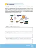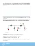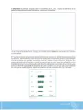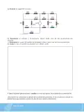

















Actividad: crear un circuito con al menos seis resistencias (configuraciones serie y paralelo), dibujarlo con valores comerciales, resolverlo de forma manual y verificarlo en un simulador.
Diseño del circuito
Eligo la fuente V = 12 \\, \\text{V} y las siguientes resistencias de valor comercial:
R_1 = 100 \\, \\Omega, R_2 = 220 \\, \\Omega, R_3 = 470 \\, \\Omega, R_4 = 100 \\, \\Omega, R_5 = 100 \\, \\Omega, R_6 = 220 \\, \\Omega.
Topología (configuración serie-paralelo):
- R_1 está en serie con todo el circuito (alimentación).
- Luego viene el grupo paralelo R_2 \\parallel R_3.
- Luego el grupo paralelo R_4 \\parallel R_5.
- Por último, R_6 en serie (retorno al polo negativo).
flowchart LR
  V["Fuente DC<br/>V = 12 V"] --> R1["R1 = 100 Ω"]
  R1 --> A["Nodo A"]
  A --> R2["R2 = 220 Ω"]
  A --> R3["R3 = 470 Ω"]
  R2 --> B["Nodo B"]
  R3 --> B
  B --> R4["R4 = 100 Ω"]
  B --> R5["R5 = 100 Ω"]
  R4 --> C["Nodo C"]
  R5 --> C
  C --> R6["R6 = 220 Ω"]
  R6 --> V
Resolución manual
Paso 1. Equivalente de cada grupo paralelo.
R_{23} = \\frac{R_2 \\cdot R_3}{R_2 + R_3} = \\frac{220 \\cdot 470}{220 + 470} = \\frac{103400}{690} \\approx 149.9 \\, \\Omega
R_{45} = \\frac{R_4 \\cdot R_5}{R_4 + R_5} = \\frac{100 \\cdot 100}{100 + 100} = \\frac{10000}{200} = 50 \\, \\Omega
Paso 2. Resistencia total (todo en serie).
R_{eq} = R_1 + R_{23} + R_{45} + R_6 = 100 + 149.9 + 50 + 220 = 519.9 \\, \\Omega
Paso 3. Corriente total por la ley de Ohm.
I_{tot} = \\frac{V}{R_{eq}} = \\frac{12}{519.9} \\approx 0.02308 \\, \\text{A} = 23.08 \\, \\text{mA}
Paso 4. Tensiones en cada tramo.
V_{R1} = I_{tot} \\cdot R_1 = 0.02308 \\cdot 100 = 2.31 \\, \\text{V}
V_{23} = I_{tot} \\cdot R_{23} = 0.02308 \\cdot 149.9 = 3.46 \\, \\text{V}
V_{45} = I_{tot} \\cdot R_{45} = 0.02308 \\cdot 50 = 1.15 \\, \\text{V}
V_{R6} = I_{tot} \\cdot R_6 = 0.02308 \\cdot 220 = 5.08 \\, \\text{V}
Comprobación de Kirchhoff: 2.31 + 3.46 + 1.15 + 5.08 = 12.00 \\, \\text{V} ✓
Paso 5. Corrientes en los ramales.
Grupo 1 (misma tensión V_{23} = 3.46 \\, \\text{V}):
I_{R2} = \\frac{V_{23}}{R_2} = \\frac{3.46}{220} = 0.01573 \\, \\text{A} = 15.73 \\, \\text{mA}
I_{R3} = \\frac{V_{23}}{R_3} = \\frac{3.46}{470} = 0.00736 \\, \\text{A} = 7.36 \\, \\text{mA}
Verificación: 15.73 + 7.36 = 23.09 \\, \\text{mA} \\approx I_{tot} ✓
Grupo 2 (misma tensión V_{45} = 1.15 \\, \\text{V}, resistencias iguales):
I_{R4} = I_{R5} = \\frac{1.15}{100} = 0.01154 \\, \\text{A} = 11.54 \\, \\text{mA}
Verificación: 11.54 + 11.54 = 23.08 \\, \\text{mA} ✓
Paso 6. Potencias disipadas y elección comercial.
P_{tot} = V \\cdot I_{tot} = 12 \\cdot 0.02308 = 0.277 \\, \\text{W} = 277 \\, \\text{mW}
| Resistor | I (mA) | V (V) | P = I^{2}R (mW) | Potencia nominal (1/4 W = 250 mW) |
|---|---|---|---|---|
| R_1=100\\,\\Omega | 23.08 | 2.31 | 53.3 | ✓ adecuada |
| R_2=220\\,\\Omega | 15.73 | 3.46 | 54.4 | ✓ adecuada |
| R_3=470\\,\\Omega | 7.36 | 3.46 | 25.4 | ✓ adecuada |
| R_4=100\\,\\Omega | 11.54 | 1.15 | 13.3 | ✓ adecuada |
| R_5=100\\,\\Omega | 11.54 | 1.15 | 13.3 | ✓ adecuada |
| R_6=220\\,\\Omega | 23.08 | 5.08 | 117.2 | ✓ adecuada |
Todas las potencias son menores que 250 \\, \\text{mW}, por lo que las resistencias de \\frac{1}{4} \\, \\text{W} son válidas.
Verificación en simulador
Procedimiento recomendado (por ejemplo, con los simuladores Falstad Circuit, CircuitLab o Tinkercad Circuits):
- Se conecta la fuente de 12 \\, \\text{V} y se ubican las seis resistencias en la topología del diagrama.
- Se miden la resistencia equivalente del conjunto (\\approx 520 \\, \\Omega), la corriente total (\\approx 23.1 \\, \\text{mA}), las tensiones de cada tramo (2.31, 3.46, 1.15 y 5.08 \\, \\text{V}) y las corrientes de los ramales (15.73, 7.36, 11.54 y 11.54 \\, \\text{mA}).
- Si las lecturas del simulador coinciden dentro del margen de redondeo, la resolución manual es válida.
R_{eq} = 519.9 \\, \\Omega; I_{tot} = 23.08 \\, \\text{mA}; tensiones 2.31, 3.46, 1.15 y 5.08 \\, \\text{V}; corrientes de ramales 15.73, 7.36, 11.54 y 11.54 \\, \\text{mA}; P_{tot} = 277 \\, \\text{mW}.